
Page 180 - 2023-Vol19-Issue2
P. 180
176 | Al-Jrew, Mahmood & Ali
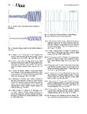
Fig. 12. Inverter Load Current with Variable Workpiece
Resistance
Fig. 14. Load Loop Current and Inverter Output Voltage
Waveform Below Resonant Frequency 40 KHz
Fig. 13. Capacitor voltage waveform with variable workpiece [8] C. Hammouma and H. Zeroug, “Enhanced frequency
resistance adaptation approaches for series resonant inverter con-
trol under workpiece permeability effect for induction
[3] Y. Wang, Y. Li, Y. Peng, and X. Qi, “Research and hardening applications,” Eng. Sci. Technol. an Int. J.,
design on igbt induction heating power supply,” Energy vol. 27, pp. 1–13, 2022.
Procedia, vol. 16, no. PART C, pp. 1957–1963, 2012.
[9] P. Omer, J. Kumar, and B. S. Surjan, “A review on re-
[4] S. Choi, C. Lee, I. Kim, J. H. Jung, and D. H. Seo, “New duced switch count multilevel inverter topologies,” IEEE
induction heating power supply for forging applications Access, vol. 8, pp. 22281–22302, 2020.
using igbt current-source pwm rectifier and inverter,”
KIEE Electr. Mach. Energy Convers. Syst., pp. 709–713, [10] R. K. Kumawat and D. K. Palwalia, “A comprehensive
2018. analysis of reduced switch count multilevel inverter,”
Aust. J. Electr. Electron. Eng., vol. 17, no. 1, pp. 13–27,
[5] O. Lucia, J. M. Burdio, I. Millan, J. Acero, and D. Puyal, 2019.
“Load-adaptive control algorithm of half-bridge series
resonant inverter for domestic induction heating,” IEEE [11] B. Nagarajan and R. R. Sathi, “Phase locked loop based
Trans. Ind. Electron, pp. 3106–3116, 2009. pulse density modulation scheme for the power control
of induction heating applications,” J. Power Electron.,
[6] Z. Waradzyn, A. Penczek, and A. Skala, “Analysis of vol. 15, no. 1, pp. 65–77, 2015.
the load current harmonics content in a series resonant
inverter for induction heating controlled using various [12] A. Cristina and O. A. Pop, “Method for detecting reso-
cases of the avc control strategy,” in Proc. 2018 Conf. nance frequency in induction heating systems,” in IEEE
Electrotechnol. Process. Model. Control Comput. Sci. 25th Int. Symp. Des. Technol. Electron. Packag. IEEE
EPMCCS 2018, pp. 1–9, 2018. Xplore, October, pp. 295–298, 2019.
[7] J. Villa, A. Mur, J. I. Artigas, L. A. Barragan, I. Ur- [13] C. Hammouma, H. Zeroug, and A. Attab, “A new ap-
riza, and D. Navarro, “Output voltage estimation of a proach for adaptive frequency in series resonant inverter
half-bridge inverter for domestic induction heating ap- for induction hardening,” in 3rd Int. Conf. Electr. Sci.
plications,” in IECON Proc. (Industrial Electron. Conf., Technol. Maghreb, Cist., pp. 1–6, 2018.
pp. 5081–5086, 2019.
[14] S. Oncu and H. Ozbay, “Simulink model of parallel
resonant inverter with dsp based pll controller,” Elektron.
ir Elektrotechnika, vol. 21, no. 6, pp. 14–17, 2015.
[15] M. H. Khazaal, I. M. Abdulbaqi, and R. H. Thejel, “De-
sign, simulation and implementation of a self-oscillating