
Page 175 - 2023-Vol19-Issue2
P. 175
171 | Al-Jrew, Mahmood & Ali
diagram for the overall control system components. While
section VI include the MATLAB simulation and modeling of
the system. Finally, section VII include the conclusion from
this work.
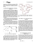
II. FIVE-LEVEL POWER SUPPLY INVERTER Fig. 2. Switching modes of five level power supply inverter
TOPOLOGY (a) Vo=+Vdc (b) Vo=+0.5Vdc (c) Vo=0 (d) Vo= -0.5Vdc (e) Vo=
-Vdc
A multilevel inverter (MLI) is an electronic power supply con-
verter that produces multiple voltage levels. It is employed in III. PWM FOR THE USED POWER SUPPLY
applications with medium and high voltages [27, 28]. Multi- INVERTER
level inverters are important because of their power quality,
harmonic amplitude reduction, and ability to provide an output The multicarrier PWM techniques have been used in this study.
voltage that is as close to a sinewave as possible. Multilevel These techniques have two categories phase shift and level
resonant inverter topologies have experienced a substantial shift. All carrier waves used in the multicarrier modulation
expansion in industrial applications in recent years due to the technique known as phase shift modulation have a phase shift
capability to deliver a voltage waveform of outstanding qual- from one carrier to another. The number of carriers is associ-
ity and reduce the current and voltage ratings of the power ated with the number of voltage levels. The same frequency
switches [29]. and peak-to-peak amplitude should be used for all carriers.
A reduced switches five-levels resonant inverter had been The relationship between voltage levels and the number
utilized as a power supply inverter for induction heating sys- of carriers in the level shift PWM technique is similar to
tem. The configuration of the series resonant multilevel in- that of phase shift. The difference between level shift and
verter explained with detailed in [30]. phase shift can be noticed in the disposition of the triangular
carrier. The phase shift and the level shift multicarrier PWM
The general layout of the conducted power supply inverter techniques have a similar relationship between the levels of
for the induction heating system (reduced switches 5-level voltage and carrier number. The level shift PWM approach
inverter) consists of two classical parts: the cascade H bridge for the employed five level inverter was the subject of this
MLI and the neutral point clamped MLI. The proposed topol- work.
ogy of 5-level power supply inverter circuit diagram is shown
in Fig. 1
Fig. 1. Five Level Inverter Power Supply Model IV. THE MATHEMATICAL MODEL
DESCRIPTION
As it clear in Figure (1), the inverter consists of six MOS-
FETs switching devices and two power diodes D1 and D2. The adopted mathematical model described with details in [1]
The input DC voltage source is divided by connecting two has been used to build the modified control system for a five
identical capacitors C1 and C2 across the source. The split level series resonant inverter in the next section. The phase
voltage is delivered to the H-bridge through two MOSFET angle between the inverter voltage vinv and capacitor voltage
switches SW1 and SW2 and two power diodes D1 and D2. vc has been adjusted to achieve the PLL concept. The phase
The five operation modes are clarified in Fig. 2 difference error between the inverter and capacitor voltages is
described as:
e(k) = x f (k) - 1 (1)
2