
Page 178 - 2023-Vol19-Issue2
P. 178
174 | Al-Jrew, Mahmood & Ali
Fig. 5. PWM Signals
Fig. 7. PLL Output Signal
Fig. 6. Inverter Gate Signals
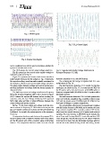
can be considered as a criteria used to determine whether the Fig. 8. Capacitor and Inverter Voltage Waveforms at
system in resonant state or not. Resonant Frequency 51.3 kHz
Fig. 10 illustrates the inverter output voltage waveform. harmonic distortion THD, overall efficiency.
The IH system has been tested under variable workpiece The conventional full bridge IH system with PLL con-
resistance as shown in Fig. 11.
Figure 12 represents the inverter load current waveform troller shown in Fig. 16.
under variable resistance for the workpiece. Fig. 13 represents The total harmonic distortion THD results for the two
the capacitor voltage waveform under variable resistance for
the workpiece, which is a purely sinusoidal voltage waveform. topologies are shown in Fig. 17. It seems that the THD for
The phase angles between voltage and current are the same, the IH system with a five-level inverter is (28.88%) which is
and their simulation waveforms match the theory analysis we lower as compared with (49.46%) for the IH system with a
discussed before full bridge inverter.
The load loop current and voltage waveforms at frequency
below the resonant frequency ( 40 KHz) is shown in Figure The total harmonic distortion THD for both systems also
(14) 14 where the system still detunes before reaching the was tested with the simplified PLL controller without using
resonance state, the Zero Voltage Switching ZVS approach LPF and the results were (29.49%), (and 49.37%) for five
fail to take place and there is phase difference between the level and full bridge IH systems respectively.
output voltage and inverter current.
In Fig. 15, the load current and voltage reach the reso- The overall system efficiency for a conventional IH system
nance state at the frequency 51.3KHz where the output volt- with full bridge inverter is (98.48%) and it remains the same
age and inverter current are in phase and the soft switching if we used the simplified PLL controller without LPF. On the
is obtained. As a result, the system operates at the resonance other hand, the overall efficiency of IH system with reduced
frequency. switches five level inverter is (89.48%) and it remains the
A comparison has been made between the proposed PLL- same if we used the simplified PLL controller without LPF.
based IH system with a multilevel inverter used in this article Even though the overall efficiency for IH system with five
and the IH system with a PLL controller using a full bridge level inverter is lower than the full bridge topology, which is
inverter. The comparison has been made in terms of total normal due to the added driving circuit and wiring, but the