
Page 176 - 2023-Vol19-Issue2
P. 176
172 | Al-Jrew, Mahmood & Ali
Where x f DC average voltage. range of integral stability gain Kc can be determined using
If the system operates in a steady-state, the DC voltage x f this Jury’s test as follow:
can be expressed as follow:
x f ss = ? = u f (2) 0 < Kc < ( 1 + a )2p 2RC (8)
p 1 - a
Where u f : the low pass filter input’s average value, PLL circuits keep tracking the resonance frequency au-
and ?: the phase difference. tomatically to maintain soft-switching under varying load
In the transient operation, the relationship between x f and conditions. The zero phase difference between the input cur-
u f can be expressed as : rent and output voltage must be obtained in resonance state to
achieve zero voltage switching ZVS.
dxf = -( 1 )x f 1 (3)
dt tf + ( )u f Zero voltage switching ZVS approach is utilized to reduce
switching losses and enhance the system efficiency, which is
tf commonly used with resonant inverter. ZVS can companied
with PLL controller to obtain the resonant frequency tracking.
Where t f is the filter time constant which is t f = RC. For The tank circuit’s resonance behavior and the frequency feed-
the resonant load of inverter operating in the steady state con- back from the PLL controller are taken into consideration by
ditions, the relation between phase difference ? and switching the ZVS control when determining the best time to switch the
period T can be given as: power transistors.
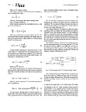
? (T ) = tan-1( RlCs 2p ) (4) The capacitor voltage vc and the inverter voltage vinv trans-
T form to square waves using Zero crossing detector ZCD. Then
the output of ZCD is applied to an XOR gate and the out-
1 - ( 2p )2 put of this gate is filtered to get a DC voltage x f which is
wo T proportional to the phase difference between the inverter and
capacitor voltages as illustrated in Fig. 3.
During transient operations in which the period T fluc-
tuates slowly, it is presumed that the equation above is ap-
proximately correct. Furthermore, Equation “(4),” is achieved
by assuming a purely sinusoidal inverter output voltage. The
following is a discretization of “(3),”:
x f (k + 1) = ax f (k) + b ?(T (k)) (5)
p
-Ts Fig. 3. The Structure of the PLL Based Control Circuit
Where a=e tf ,b= (1-a) The switching frequency is adjusted after comparison be-
tween the average DC voltage (x f ) and a value of 90 degrees,
During the heating process, the induction heating system to make the phase difference zero. When this requirement is
detunes and the relation between the next resonance periodical fulfilled, the voltage and current of the inverter are assured to
time T (k+1) and the previous one T (k) can be expressed as be in phase.
follows:
V. DESCRIPTION OF THE CONTROL SYSTEM
T (k + 1) = T (k) + Kce(k + 1) (6)
The structure of the PLL based modified control circuit is
Where Kc is the integral gain. The closed-loop equation shown in Fig. 3 as an example of how it works. The system
can be expressed as: block diagram consists of the following parts: Zero Crossing
Detector ZCD which responsible for detecting the variation
T (k + 1) = T (k) + Kc (ax (k) + b ? (T (k)) - 1 ) (7) from positive to negative level of the sinusoidal voltage wave-
p 2 forms. Exclusive OR gate, where the output from this logic
f
The jury test of stability used for discrete systems is a
simple form of the Routh-Hurwitz algorithm which checks
if the polynomial roots are enclosed by the unit circle. The