Page 89 - IJEEE-2022-Vol18-ISSUE-1
P. 89

Ali & Rashid                                                                                                                                                                                 | 85

                                                                                                       B. Mathematical model for Autotuning PID Controller.

                                                                                                       A PID controller consists of three terms: the

                                                                                                       proportional (P) term, the integral (I) term, and the derivative

                                                                                                       (D) term. In an ideal form, the output u(t) of a PID controller

                                                                                                       is the sum of the three terms,

                                                                                                              ??(??)  =   ???? ??(??)  +  ????  ?0??  ??(??)????     +  ???? ????  ????(??)  (6)
                                                                                                                                          ??1                                        ????

                                                                                                       where e(t) = r(t) - y(t) is the feedback error signal between

                                                                                                       the reference signal r(t) and the output y(t), and ??D is the

                                                                                                       derivative control gain. The Laplace transfer function of the

                                                                                                       PID controller is

                                                                                                                      ??(??)  =  ??(??)   =     ???? (1  +    1      +  ???? ??)             (7)
                                                                                                                                 ??(??)                      ??????

                                                                                                       The P action (mode) adjusts the controller output

                                                                                                       dependent on the error magnitude. An I action (mode) may

                                                                                                       eliminate the steady-state offset, but the D action anticipates

                                                                                                       the future trend (mode) (mode). These helpful functions are

                                                                                                       adequate for a broad variety of process applications, and the

                                                                                                       features' transparency leads to widespread user acceptance

                                                                                                       [23].

                                                                                                       To design the PID controller, can assume that two

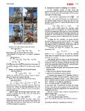
                  Fig. 3: D5204 in Basrah Refinery.                                                    estimated frequency response points from the relay testing

     Balance over Total Process System (PS total):                                                     data are the fundamental frequency Gp(j?1), ?1 = 2p/N?t
                                                                                                       and Gp(j?2). If there is no disturbance in the system, then ?2
                                                                                                       is selected as 3?1.Otherwise, ?2 is selected as 2?1.

     - Total mass balance:                                                                                    Converting the ideal PID structure into another

                       ????    =  ??2? ??  +  ??2? ??   -     ???3   -    ???4                  (1)    polynomial form:
                       ????
                                                                                                                                 ??(??) = ??2??2+??1??+??0                                   (8)
M: the total mass, ??? ??: the mass flow of current i.                                                                                                   ??
                                                                                                       where Kc = c1, tI = c1/c0 and tD = c2/c1, the PID controller
With subscript V for vapor and L for liquid in multiphase

currents.                                                                                              design using the estimated frequency response is to find the

     - Energy balance:                                                                                 parameters c2, c1 and c0.

      ????  -    ????  +  ??2? ??  *  ?^?2??  +      ??2? ??  *   ?^?2??   -  ???3  *  ?^?3  -              Automatically adjust PID gains in real time depending
      ????       ????                                                                                  on the expected plant frequency response from a closed-loop
                                  ??????                                                               experiment. Utilize the Frequency Response Estimator to do
            ???4  *    ?^?4    =   ????                                                         (2)    a real-time experiment-based estimate on a physical plant.
                                                                                                       To acquire a frequency response estimate.
With  ????  the  heat     flow     and     ????    the  workflow           of   the    system,  ?^???  ? Injects sinusoidal test signals into the plant at the nominal
      ????                                 ????

the specific enthalpy of current ET the total energy of total

PS.

? Balance over Liquid Process System (PS liquid):                                                      operating point.

     - Total mass balance:                                                                             ? Collects response data from the plant output.

                       ??????  =        1            *  (??2? ??  -  ???4)                      (3)    ? Computes the estimated frequency response.
                       ????        ????*??*??2

With ???? the liquid level in the tank, ???? density of phase ??                                            A recursive least squares (RLS) algorithm [24-26] to

(liquid or vapor), and r radius of the tank.                                                           compute the estimated frequency response. Assume that the
                                                                                                       plant frequency response is ??(????) = ??????? . When a signal
? Balance over Vapor Process System (PS vapor):                                                        ??(??) = ????????(????) excites the plant, the steady-state plant is
                                                                                                       ??(??) = ????sin(???? + ??), which is equivalent to:
     - Total mass balance:                                                                             ??(??) = (??????????)????????(????) + (??????????)????????(????)

      ????  =     1    *  ( ??*??   *     ??2? ??  -    ??*??     *  ???3  -    ??  *  ??????)  (4)    At any given time, ????????(????) and ????????(????) are known,
      ????       ????                                   ??????                                         therefore, they can be used as regresses in an RLS algorithm
                            ??????                                                      ????           to estimate ?? cos(??) and ??sin(??) from the measured plant
                                                                                                       output y(t) at run time.
With P the pressure in the vapor phase inside the tank, R the
                                                                                                            When the excitation signal contains a superposition of
universal gas constant the operating temperature, ?????? the                                           multiple signals, then:
molecular mass of vapor, and ???? the volume of vapor phase                                            ??(??) = ??1 sin(??1??) + ??2 sin(??2??) + ?

inside the flash tank.                                                                                      In this case, the plant output becomes:
                                                                                                       ??(??) = (??1????????1)??1 sin(??1??) + (??1 sin ??1)??1 cos(??1??) +
     Liquid or vapor flow through output flash tank valve,                                             ?

required to calculate ???3 and ???4 , vapor and liquid flows                                           (??2????????2)??2 sin(??2??) + (??2????????2)??2 cos(??2??) + ?

exiting the flash tank:

                       ??? ??  =  ??????   *   ????  *  v?????    *  ????                       (5)
                                              100

With ?????? the coefficient of valve for phase i, ???? the valve

opining percentage, and ????? the pressure drop through the

valve acting over phase ??.In valve sizing ???? is taken equal

to 50% for nominal or design flow.
   84   85   86   87   88   89   90   91   92   93   94