
Page 88 - IJEEE-2022-Vol18-ISSUE-1
P. 88
84 | Ali & Rashid
The Naphtha HDS with Stabilization and Splitting Unit
Fig. 2: DRUM D5204 schematic diagram.
(U7501) is designed for feedstock preparation for newly built
Catalytic Reforming and Isomerization Units within Basrah III. MATHEMATICAL MODEL
Refinery. Process modeling is a useful tool for doing process
synthesis, analysis, or operational optimization. There are
Naphtha feed from U7501 to a Catalytic Reforming unit three types of models: black box, white box, and gray box
typically contains C6 to C11 paraffin, naphthenic, and models. In this essay, the first and second classes are not
aromatics. The purpose of this reforming process is to discussed. It is because experimental models are dependent
produce high-octane aromatics from naphthenic and paraffin on data that they lack the specialized process knowledge that
for use as a high-octane gasoline blending component. they are called " experimental ". Physical models and white
boxes are utilized because they demand thorough
The D5204 vapor phase constitutes hydrogen comprehension of the laws and theories guiding all of the
production. Part of the hydrogen production upstream of the actions involved. Semi physical models based on mass and
pressure control valve is used in the naphtha hydrotreatment energy balances are used here to simulate the flash process.
unit as make-up that is all noticed in Fig. 2. The remaining A. Mathematical model for RD D5204 (separator or flash
hydrogen-rich gas is routed to the hydrogen-rich gas network drum).
at 24 bar g. The separated liquid from RD D5204 is sent By using the flash drum (separator drum) expressed in
under level control to the stabilization section. The work Fig. 3 that has the following specification data:
preview descriptor for RD D5204 emphasizes the Item Tag: 7502-D5204. The mixture is available at (25)
importance of strong performance management for levels bar, (45) oC. At steady state, the molar inlet is (1159.01)
and pressures to provide optimal functioning. kmole/h or 48141 kg/h and gravity 759 kg/m3. This stream
will be in two-phase the liquid by 85% and vapor by 15%
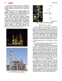
Fig. 1: UNIT 7501 in Basrah Refinery. with pressure (25). The physical separator occurs in a flash
tank of 5.2 m in height and 1.6 m in diameter. Liquid-vapor
equilibrium consolidates in the flash drum. Because there is
enough difference between the relative volatility, the current
liquid that leaves the tank for the bottom contains a large
percentage of (reformate + LPG + off-gas) at pressure 25.5
bar and gravity 834.9 kg/m3 also from top leaves rich gas
(65-70 %) H2 + C1, C2, C3 … at pressure 25 bar.
To apply the conservation principle to all determined
Process systems. Over each PS, it is advised to do the
following balances: one total mass balance, n component
mass balance, and total energy balance. When there are
significant pressure or density variations in the process,
momentum balancing is utilized. The Dynamics Balance
Equations (DBE) are balance equations that assume that all
balances are originally dynamic. If the process contains
certain static characteristics, some of these can be converted
to static equations. The mass and energy balance is
established in the flash process being discussed here [8].