
Page 58 - IJEEE-2022-Vol18-ISSUE-1
P. 58
54 | Al-Jrew, Mahmood & Ali
The output voltage waveform and the total harmonic
distortion for the conventional neutral clamped multilevel
inverter is illustrate in Fig. 10.
(a)
(a)
(b) Fig.10: (a) Output voltage w(abv)eform for NCI (b) THD for
Fig.8: (a) Proposed five level inverter topology NCI
(b) PWM control The simulation results for the two conventional
The comparison and analysis has been made among multilevel inverter topologies shows that the total harmonic
those three topologies in terms of total harmonic distortion distortion for the cascade H-bridge multilevel inverter value
THD, efficiency and RMS voltage obtained using different is 29.23% while the THD for the neutral clamped multilevel
technique of level shift PWM. inverter is 29.01%. The PWM technique used in these two
The output voltage waveform and the total harmonic topologies is phase disposition (PD) modulation technique.
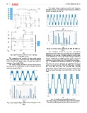
distortion for the conventional cascade H-bridge multilevel Fig. 11 illustrates the simulation results for the proposed
inverter is shown in Fig. 9. five-level. As can be observed, the suggested five level
multi-level inverter has the THD (29.47%) while the THD
for CHB and NCI MLI are (29.23% and 29.01%)
respectively, which is almost close. To reduce the harmonics
for the proposed topology, it’s recommend to use low pass
filter.
(a)
(a)
(b) (a)
Fig. 9: (a) Output voltage waveform for CHB (b) THD for Fig. 11: Results of proposed five level MLI
(a) Output voltage waveform (b) Output current waveform
CHB (c) switching gate pulses (d) four carrier signal (e) THD.