
Page 55 - IJEEE-2022-Vol18-ISSUE-1
P. 55
Al-Jrew, Mahmood & Ali | 51
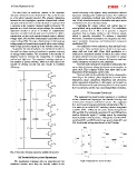
The third form of multilevel inverter is the capacitor overall efficiency of the system. Many modulation methods
clamped multilevel inverter illustrated in Fig. 3, also known have been introduced for multilevel inverter. For multilevel
as a fly-wheel capacitor inverter .The primary distinction inverters, modulation methods and control paradigms like
between the two topologies, capacitor clamped and a diode sine PWM, selective harmonic elimination and space vector
clamped multilevel inverter is that the diode is replaced with modulation have been developed [22].
a capacitor in the capacitor clamped multilevel inverter. To
generate an n-level staircase output voltage, the number of Controlling the output voltage and current may be
capacitors needed is (n-1). A number of supplemental accomplished using modulation methods. The modulation
capacitors are added and clamped across switches in a ladder signal's primary aim in MLI is to generate a stepped
construction, so that each capacitor branch carries a distinct waveform that is closely similar to the reference signal,
voltage value, which allows mathematical exploitation of the which is typically sinusoidal. To achieve a sinusoidal
output voltage [20]. The major disadvantage in this topology waveform, modulation techniques are categorize into three
is large number of capacitors is required when output voltage types: amplitude, frequency, and fundamental component
level is high also the complexity in the inverter control [21]. modulation [23].
In general, the only drawback of a multilevel inverter is The multicarrier PWM methods has been utilized in this
the need for a large number of switches to produce a variety present work. These methods can be divide in to two types,
of voltage levels number. This increment in the number of phase shift and level shift. Phase Shift modulation is a
switches leads to increase the complexity of controlling multicarrier modulation method in which all carrier waves
method and high cost. The suggested topology employs a are phase shifted from one another. The number of voltage
low number of power switches, which not only reduces the level relates to the number of carriers. All carriers must have
number of driving circuits but also results in excellent similar frequency and peak-to-peak amplitude.
efficiency.
The level shift multicarrier modulation method have the
same relation between voltage levels and carriers number as
phase shift. This technique differs from phase shift in the
disposition of the triangular carriers [24].
The level shift can be subdivide into three subcategories
according to the carriers’ phase disposition, Inverted phase
disposition, phase opposition disposition and alternative
phase opposition disposition. In this paper, we focused on
these techniques and compared among them for the proposed
five level inverter and the two conventional MLI topologies.
IV. PROPOSED TOPOLOGY
The suggested five-level inverter topology is a combined
of two conventional topologies, the cascade H-bridge and
neutral point clamped multilevel inverter. The suggested
five-level inverter's circuit schematic is illustrated in Fig. 4.
It is made up of six MOSFET switching devices designated
as (SW1, SW2... SW6) and two power diodes designated as
(D1 and D2). Two identical capacitors (C1 and C2) has been
used to divide the input DC voltage source by connecting
them in parallel with the source. Through the two MOSFET
switches (SW1 and SW2) and the two power diodes (D1 and
D2), the divided voltage transferred to the H-bridge.
Fig.3: Structure of flying capacitor multilevel inverter Fig.4: Proposed five level inverter
III. TYPES OF MODULATION TECHNIQUE
The modulation techniques play an important rule for
multilevel inverter since they are directly related to the