
Page 57 - IJEEE-2022-Vol18-ISSUE-1
P. 57
Al-Jrew, Mahmood & Ali | 53
Fig.5: Operation modes of proposed five-level inverter (b)
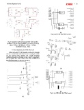
(a) Mode 1 (Vout=+Vdc) (b) Mode 2 (Vout)=+1/2Vdc (c) Fig.6: (a) NC-MLI (b) PWM control.
Mode 3 (Vout= 0) (d) Mode 4 (Vout= -1/2Vdc) (a)
(e) Mode 5 (Vout= -Vdc).
V. DESIGN, SIMULATION AND RESULTS
In this study, MATLAB/Simulink is utilized to simulate
the two conventional multilevel inverter topologies which
are the neutral point clamped and cascade H-bridge
multilevel inverters as illustrate in Figs. 6 and 7 respectively.
The proposed five level inverter has been simulated in
MATLAB/Simulink as illustrated in Fig. 8.
(b)
Fig.7: (a) CHB-MLI (b) PWM control
(a)