
Page 56 - IJEEE-2022-Vol18-ISSUE-1
P. 56
52 | Al-Jrew, Mahmood & Ali
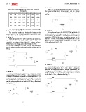
TABLE I 3- Mode 3:
SWITCHING STATE OF PROPOSED FIVE-LEVEL INVERTER When the two MOSFET (SW3 and SW5) are turned on,
TOPOLOGY. the output voltage level becomes zero, and the voltage
SW1 SW2 SW3 SW4 SW5 SW6 Vout supplied across the load terminals is Vdc=0, as illustrated in
ON ON ON OFF OFF ON +Vdc Fig. 5c.
ON OFF ON OFF OFF ON +1/2Vdc (c)
4- Mode 4:
OFF OFF ON OFF ON OFF 0
At negative half cycle, the MOSFET SW2 and diode D1
Off ON OFF ON ON OFF -1/2 Vdc and are turned on the output voltage level -1/2Vdc. In this
configuration, the H-bridge is connected in parallel with the
ON ON OFF ON ON OFF -Vdc capacitors (C2). Furthermore, the voltage across the H-
bridge is -1/2Vdc. The MOSFET switches SW4 and SW5 are
The switching arrangement at various output voltage then activated, and the voltage supplied to the load is -1/2
levels is indicated in Fig. 5. Vdc, as illustrated in Fig. 5d.
The operation modes can be describe based on the
present path for the switches operation sequence at each
mode and it can be stated as follows:
1- Mode 1:
When the two MOSFET (SW1 and SW2) are turned on,
the output voltage level Vo=+Vdc, while H-bridge is
provided by energy from the DC voltage source.
Furthermore, the voltage across the H-bridge is +Vdc.
The MOSFET switches SW3 and SW6 are then activated,
and the voltage supplied to the load is +Vdc, as illustrated in
Fig.5a.
(a) (d)
2- Mode 2: 5- Mode 5:
When the diode D2 and MOSFET SW1 are turned on the When the two MOSFET (SW1 and SW2) are turned on,
output voltage level Vo=+1/2Vdc. In this configuration, the the output voltage level Vo = -Vdc, while H-bridge is
H-bridge is connected in parallel with the capacitors (C1). provided by energy from the DC voltage. Furthermore, the
Furthermore, the voltage across the H-bridge is +1/2Vdc. voltage across the H-bridge is -Vdc. The MOSFET switches
The MOSFET switches SW3 and SW6 are then activated, SW4 and SW5 are then activated, and the voltage supplied
and the voltage supplied to the load is +1/2 Vdc, as illustrated to the load is -Vdc, as illustrated in Fig. 5e.
in Fig. 5b.
(e)
(b)