
Page 54 - IJEEE-2022-Vol18-ISSUE-1
P. 54
50 | Al-Jrew, Mahmood & Ali
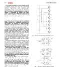
Fig. 1: Structure of diode clamped multilevel inverter.
The next section will take an overview about the concept
of multilevel inverter and discuss the conventional Fig. 2: Structure of cascaded multilevel inverter
topologies characteristics, their advantages and
disadvantages. Section III will discuss the modulation
techniques used to control the inverter switches turning on
and off. In section IV, details description about the proposed
topology, it’s configuration and operation mode. While
section V include the MATLAB simulation for the system
and the obtaining results from it. Finally, section VI include
the final conclusion from this comparison work.
II. MULTILEVEL INVERTER CONCEPT
The aim of multilevel inverters is to create a smoother
stepped of waveform of an AC signal with reduced dv/dt and
harmonic distortion when compared to conventional two
level inverters. The importance of multilevel inverter
manifested in reducing the harmonic distortion for some
application needed this feature in output voltage. This
feature cannot be reached when using two level inverter.
The multilevel concept of inverters had been introduced in
the year 1975 to overcome the drawbacks in industrial
application inverters like lower efficiency, high cost and
switching losses. This inverter concept starts with three
levels. Multilevel inverter can deliver AC voltage waveform
by using many DC voltage configuration [16].
The output waveform of multilevel inverter takes the form
of stair case whose fundamental component is a sinusoidal.
There are two categories of inverters used in power
application; voltage source inverters and current source
inverters.
For multilevel topologies, the VSI has advantages such as
the reduction in dv/dt, harmonics, electromagnetic
interferences and filter size [17]. The major three topologies
of voltage source inverter are the diode or neutral clamped
point inverter, flying capacitor clamped multilevel inverter
and finally the cascaded H-bridge multilevel inverter.
Neutral clamped multilevel inverter as a compare with
other topologies has some advantage like when higher
number of output level achieved, harmonic will be low. The
main structure of this type is shown in Fig. 1.
The main drawback is that as the output voltage level number
rises, the clamping diode is used excessively, making it hard
to manage the real power flow of the individual inverter in a
multi-inverter system [18].
Cascaded H-bridge (CHB) is another topology which also
called cascaded multilevel inverter, no diodes or capacitors
used in this topology. The CHB topology consist of number
of bridge cells and when used in modular DC/AC inverter,
the inverter system will be more reliable. The DC voltage
sources are separated in this topology as illustrate in Fig. 2
and increases proportionally with number of produced output
voltage level which is the major disadvantage of this
multilevel inverter topology [19].