
Page 121 - IJEEE-2022-Vol18-ISSUE-1
P. 121
Jasim & Jasim | 117
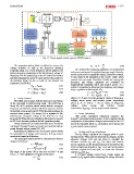
Fig. 11: The proposed control system of BESS inverter
The resynchronization block is utilized to recover the ??2 - ??1 ? - ???? (18)
??1
voltage deviation as well as the frequency deviation
As a result of the foregoing equations, it is evident that
computed using PLL. These deviations will be added to the
real power can be used to regulate the power angle. Reactive
primary droop to compensate for the difference in voltage or
power can be used to control the voltage. Frequency control,
frequency. The DC power (Pdc) on the DC side of the inverter
and (the instantaneous active (??) and reactive (??) powers) in in turn, leads to the regulation of the power angle, which
dq reference frame on the AC side of the inverter are controls the real power flow [43]. Finally, the microgrid's
represented as [38-40], frequency and voltage amplitude are controlled by
?????? = ???????????? (12) independently regulating active and reactive power. As a
(13)
?? = 3 (???? ???? + ???? ???? ) result, it is possible to determine the frequency and voltage
2 (14)
3 droop regulation as follows [44-47]:
2
?? = (???????? - ???? ???? ) ?? = ???? + ??????(?? - ????) (19)
?? = ???? + ??????(?? - ????) (20)
? Droop Control where ??, ??, ?? and ?? are the measured values of frequency,
The BESS must regulate both the frequency and voltage voltage, active power and reactive power respectively
where ???? , ???? , ???? and ???? = the set values of frequency,
of the microgrid in grid-forming mode. The BESS has a
voltage, active power and reactive power
droop P/F of 0.5 percent, which means that the microgrid
frequency can fluctuate between 50.25 Hz (inverter absorbs respectively. ??????, ?????? = droop proportional constants.
its nominal active power) and 49.75 Hz (inverter produces its
nominal active power). The droop Q/V is adjusted to 3%, ? Power Calculation
allowing the microgrid voltage at the PCC bus to vary The power calculation subsystem computes the
between 609 Vrms (inverter absorbs its full inductive power) inverter's active and reactive power. It also computes the dq
to 582 Vrms (inverter produces its full capacitive power). components of three-phase voltages and currents at the PCC
bus of the microgrid where ???? can regulate active power and
Droop control has two functions in this study: it controls ???? can control reactive power.
real power through frequency control and controls reactive
power through voltage control [41, 42].
Regulating the system's real and reactive power allows ? Voltage and Power Regulators.
The dq voltage regulators are engaged while in grid-
for manipulation of voltage and frequency. A droop control forming mode. They take the observed dq voltages and the
reference voltage Vref and use them to calculate the
equation is formed as following: reference currents Idref and Iqref. The active and reactive
power regulators use the measured power (P and Q) from the
The actual and reactive power in a transmission line are BESS primary bus (shown in Fig. 1), as well as the power
reference signals Pref and Qref, to create the reference
designed as follows: currents Idref and Iqref.
A PI-based voltage control loop creates output dq
?? = ??1??2 ???????? (15) current (Id, Iq) signals while comparing the voltage reference
(16)
??
?? = - ??1??2 ???????? + ??12
?? ??
The angle of the power (??) is very low so ???????? = ?? and
???????? = 1. Then equations (15) and (16) becomes,
?? = ???? (17)
??1??2