
Page 120 - IJEEE-2022-Vol18-ISSUE-1
P. 120
116 | Jasim & Jasim
For the typical three phase inverter model, the
mathematical modeling of a three-phase grid-connected PV
system is as follows.
???? = ???? ???? + ???? ?????? + ??????
????
???? = ???? ???? + ???? ?????? + ?????? (5)
????
???? = ???? ???? + ???? ?????? + ?????? }
????
where ????, ????, ???? are the inverter side voltages,
??????, ??????, ?????? are the grid side voltages and ????, ????, ???? are the
inverter output currents, ???? and ???? are the resistor and
inductor of the LC power filter.
Equation (5) may be written as the current equation (6)
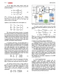
?????? ???? 1 1 Fig.10 suggested control strategy of three phase PV inverter
???? ???? ???? ????
= - ???? - ?????? + ????
?????? - ???? 1 1 The voltage control PI regulator is given by eqn. (9),
???? ???? ????
= ???? ???? - ?????? + ???? (6) and the current control PI regulators are given by eqns. (10)
?????? - ???? 1 1 and (11).
???? ???? ????
= ???? ???? - ?????? + ???? } ????-?????? = (?????????? + ??????????/??) (??????-?????? - ??????) (9)
The inverter control's primary function is to transmit ???? = (?????????? + ??????????/??) (????-?????? - ????) (10)
the maximum amount of solar energy produced into the grid
and to manage the dc-link voltage. As shown in Fig. 10, the ???? = (?????????? + ??????????/??) (0 - ????) (11)
suggested control strategy is based on two loops. The dc-link
voltage is in the outer loop, while the inverter output current Where ?????????? and ?????????? are the proportional and integral
is in the inner loop. Around the inverter, three basic gains of the PV voltage loop control, and for the current loop
command blocks appear: the current loop, the dc-link voltage control are ?????????? and ??????????.
controller, and the phase-locked loop (PLL).
3) Battery Energy Storage System (BESS) Model
In electrical engineering, the aß transformation or A battery device, an LCL filter, a two-level converter,
Clarke transformation is a mathematical transformation used and a 480V/600V transformer comprise the Battery Energy
Storage System model. The BESS also has a control system
to make three-phase circuit analysis easier. It's comparable shown in Fig. 11 that generates voltage reference (Vref) to
the PWM generator that controls the converter output, as
to the dq0 transformation in terms of concept. One of the well as a control signal (open/close) to the grid breaker.
most useful applications of the aß transformation is the
The battery system model is made up of 3.2V, 14Ah
generation of the reference signal required for space vector Lithium-ion Iron Phosphate (LFP) cells. They are grouped in
many cell modules (72 modules of 4 cells) that are linked in
modulation control of three-phase inverters. Firstly, here the series to make a 922V battery string. Our model's battery
system consists of 80 battery strings connected in parallel to
Clarke Transform block converts a three-phase current and produce a system rated at 1 MWh.
The following are the primary components of the BESS
voltage time-domain components in (abc) reference frame to control system model:
components in a stationary (aß) reference frame. The Clarke
transform is implemented as follows:
-0.5 ??
?? = 2 1 -0.5 ] [??]
[??] 3 [0 - v3 ?? (7)
v3 2
2
In the abc reference frame, the components of the three- ? Unit of Resynchronization
Without synchronizing the microgrid with the
phase system are a, b, and c. In the stationary reference distribution system, out-of-phase reclosing will occur,
frame, a and ß are the components of the two-axis system. resulting in extremely high inrush currents. To avoid this, the
resynchronization device will first bring the microgrid
The stationary reference frame of voltage signals are voltage into phase with the distribution system voltage
before re-closing the grid breaker. This will guarantee a
applied to PLL block to compute the phase difference angle. smooth reconnection to the distribution system. The
synchronization procedure will take 3 seconds. During that
Then a transition of (aß) Clarke components in a fixed time, PI regulators will gradually bring the microgrid voltage
and frequency up to par with the main grid.
reference frame to (dq) Park components in a rotating
reference frame is performed by the (aß) to dq block using
equation (8).
[????] = [-???????????????? ????????????((????))] ?? (8)
[??]