
Page 119 - IJEEE-2022-Vol18-ISSUE-1
P. 119
Jasim & Jasim | 115
As inputs to the MPPT fuzzy logic controller, the error The fuzzy rules are written as:
E(n)=?P/?V and the change in voltage ?V (the user has the ? If dv is Neg. and dp/dv>0 then ?D is 1
? If dv is Neg. and dp/dv<0 then ?D is -0.2
option to choose the inputs of this Controller) were utilized. ? If dv is Pos. and dp/dv>0 then ?D is 0.1
? If dv is Pos. and dp/dv<0 then ?D is -0.8
Since dP/dV diminishes at MPP, then:
The duty ratio change (?D) is added to the PWM generator's
E(n) = P(n)-P(n-1) (3) input, which consists of an integral and comparator with a
(4) saw tooth wave as a reference voltage.
V(n)-V(n-1)
The power declines over time, with the most power
?V(n) = V(n) - V(n - 1) accessible at lower temperatures, as seen in (Beriber and
Talha, 2013 [35]). Furthermore, according to (Younis et al.
The fuzzy logic controller output, which is generally a 2012 [36]), when a PV panel is directly connected to a load,
change in duty ratio (?D) of the power converter, may be the load impedance defines the PV module's operating state,
searched up in a rule base table if E and ?V are computed and only the optimal load allows the PV module to collect
the maximum power. Lodhi et al. 2017 [37] offered a
and translated to linguistic variables. The linguistic variables comparison of the P&O approach with the Incremental
(allocated to ?D for various combinations of E and ?V) are Conductance (IC) method under stable and dynamic weather
conditions. However, as compared to the P&O technique, IC
determined by the power converter in use as well as the user's hardware design is more difficult. While P&O systems are
understanding. The fuzzy logic controller output ?D is straightforward, the operating point oscillates about MPP,
resulting in considerable power loss.
changed from a linguistic variable to a numerical variable
In current work, there are two operation modes of the
during the defuzzification stage [34]. boost converter to regulate the PV array: maximum power
point tracking (MPPT) and curtailment. In mode 1, a fuzzy
Fuzzy logic-based MPPT controllers have proven to be logic based MPPT algorithm calculates the boost converter
duty cycle to ensure maximum power extraction from the
effective in a variety of atmospheric circumstances. array for a given solar irradiation. The duty cycle of the boost
converter is adjusted to follow the active power reference in
However, their success is heavily reliant on the user's or curtailment mode as shown in Fig.9.
control engineer's ability to select the appropriate error
The boost converters' output voltage (DC bus voltage)
computation and create the rule basis table. Whereas is 1000V. A three-level inverter (with a switching frequency
of 2340 Hz) transforms the 1000 V DC to about 500 V AC.
increasing the number of linguistic variables improves the The inverter is regulated by a DC voltage regulator, whose
function it is to keep the DC link voltage at 1000V no matter
output accuracy, it also increases the system's complexity. how much active power the PV arrays supply. To link the
inverter to the microgrid, an LC power filter can be adopted
Fuzzy technique is used to obtain the MPP in this paper, and in AC side and a 1-MVA 480V/600V three-phase coupling
a Proportional Integral (PI) controller is adopted to control transformer is utilized (see Fig.1).
the boost when a curtailment operation is required.
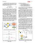
+_ dv Fuzzy MPPT
Fuzzification
Delay ?
Fuzzy rule
V (k) × P (k) × dp Defuzzification
I (k) +_ dv
Delay
?D
Fig.7: the fuzzy logic controller's block diagram
Fig.8: Membership Functions: (a) Change in voltage (b) Fig.9 control method of PV-connected boost converter
Change in dp/dv cascaded with inverter for MPPT and power curtailment
modes.