
Page 188 - 2023-Vol19-Issue2
P. 188
184 | Gaid & Ali
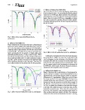
C. Effects of Feeding Line Width (Fw)
The return loss curves for various feeding line width values
(Fw) are shown in Fig. 6. It can be observed that the optimal
value for Fw is 0.9992 mm, which yields the best performance
with satisfactory return loss values for the desired frequency
bands. When Fw is set to 0.5992 mm, a degradation in return
loss values is observed in all three frequency bands, with the
resonance shifting beyond the 38 GHz frequency and below
the 28 GHz band.
Fig. 4. Effect of inset gap width (Wg) on the S11
performance.
B. Effects of Slot Width (Sw) Fig. 6. Effect of the slot width (Sw) on the S11 performance.
Figure 5 illustrates the return loss performance of the proposed
antenna for various I-shaped slot width values (Sw). At an Sw Additionally, the bandwidth of the third band decreases.
of 0.1 mm, the antenna covers only the 28 GHz band with a Increasing Fw to 1.5992 mm causes the second band at 38
return loss value of approximately 28.5 dB and a second band GHz to disappear, and the resonance in the first band shifts
around 43 GHz. Increasing Sw to 0.2 mm generates three beyond 28 GHz while the resonance in the third band moves
bands, including the 28 GHz and 60 GHz bands, with a wide below 56 GHz with a significant drop in its bandwidth. There-
bandwidth spanning from 51.7 GHz to about 64 GHz. When fore, the optimal value for the Fw parameter is determined to
Sw is further increased to 0.3 mm, the resonance frequency in be 0.9992 mm, which ensures the desired frequency bands are
the second band shifts to 40 GHz with a reduction in return established with acceptable return loss values.
loss value, and the resonance frequency in the third band shifts
with a significant decrease in return loss value. Therefore, 0.2
mm is determined to be the optimal value for this parameter.
Fig. 5. Effect of the slot width (Sw) on the S11 performance. D. Effects of slot length (Lso)
Figure 7 illustrates the S11 performance of the proposed de-
sign for various Lso values. It can be observed that Lso is a
significant factor, and changing its value results in a noticeable
difference in S11’s performance. When Lso is set to 0.8 mm,
the design operates in the target 28/38/60 GHz frequencies,
as shown by the blue solid line curve. If the value of Lso is
increased to 1 mm, the return loss at 28 GHz falls to around 13
dB, while the resonant frequency in the second band shifts to
36 GHz. In addition, the resonance in the third band changes
to 53 GHz with a slight decrease in return loss value, but the
bandwidth remains the same. If the value of Lso is decreased
to 0.6 mm, the resonance in the first band shifts below 27
GHz, and the second band, it shifts to 40 GHz. The return loss
values of the first and second bands also increase. Lowering