
Page 187 - 2023-Vol19-Issue2
P. 187
183 | Gaid & Ali
TABLE I.
DIMENSIONS OF THE FINAL OPTIMIZED DESIGN
Parameter Dimension (mm) Parameter Dimension (mm)
Sub length (Ls) 8 Feed length (Lf) 3.6
Sub width (Ws) 8.5 Inset width (Wg)
Inset length (Lg) 0.395
Sub thick 0.508 Slot width (Sw) 1.002
Pat length (Lp) 4.24 Horizontal Slot length (Sl) 0.2
Pat width (Wp) 3.288 Vertical. Slot length (Lso) 1.4
Pat thickness 0.035 p-shaped slot position (X) 0.8
Feed width (Fw) 0.9992 1.5
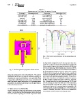
Fig. 3. The return loss performance for the design phases of
the antenna.
Fig. 2. The final optimized proposed tri-band antenna. the Wg variable is adjusted to 0.195 mm, the return loss value
at 28 GHz is reduced, causing the bandwidth surrounding 28
study was conducted on some critical factors. This section GHz to vanish. However, the return loss levels at 38 GHz and
investigates the effects of varying the following variables on 56 GHz are improving. When the Wg value increases to 0.395
the proposed antenna’s performance: inset gap width (Wg), mm, the return loss value at 28 GHz increases to around 15
I-shaped slot width (Sw), slot length (Lso), microstrip feed dB while slightly decreasing at 38 GHz and 56 GHz to about
width (Fw), and p-shaped slot location (X). By adjusting these 18 dB and 26 dB, respectively. Notably, there is a significant
parameters, the antenna’s performance can be optimized to increase in bandwidth at 56 GHz, which is beneficial as we
achieve the desired results. aim to achieve the widest bandwidths possible. To determine
if the return loss values and bandwidth continue to improve,
A. Effects of Inset Gap Width (Wg) the Wg variable is further increased to 0.595 mm. However,
Figure 4 illustrates the return loss performance for various Wg Fig. 4 shows that while the return loss values at 28 GHz and
values. It can be observed that this parameter affects the return 56 GHz increase, the return loss value at 38 GHz deteriorates,
loss value without impacting the resonant frequencies. When and the bandwidth at 56 GHz also shrinks. If the Wg value
continues to increase, it is expected that the bandwidth at 38
GHz will vanish, and the bandwidth at 56 GHz will further
contract. Therefore, the value of 0.395 mm is deemed the
most suitable and ideal value for the Wg parameter.