
Page 232 - 2024-Vol20-Issue2
P. 232
228 | Abdul Zahra & Wali
asymptotic stability is proved by achieving the Lyapunov ??
theorem of the controlled system. The proposed controller
was implemented using FPGA depending on the Xilinx block ??2 Link 2
sets using system generator through Integrated Software Envi- ??2
ronment (ISE 14.7) and MATLAB software. To address the
design parameters problem by designing STSMC controller ??1
which based on FPGA which have direct effect on dynamic
performance for the controlled robotic system, the optimiza- ??1 Link 1 ??
tion techniques are introduced to tune the parameters of a
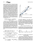
designed controller. In the present paper, the Chaotic PSO Fig. 1. Two – DoF Robot Manipulator Block Diagram
algorithm has been used to find the optimum gains of the
proposed control scheme to improve its performance based on
robotic system. The paper organizes as follows: the mod-
eling of 2 - Links robot manipulator is presented in Sec. III.
Sec. IV. describes the design of the proposed controller based
on FPGA. Sec. V. is dedicated to employ the Chaotic PSO
Algorithm to have the best optimal parameters of the sug-
gested controller. Sec. VI. gives the simulation results for
comparison purposes. Finally, the conclusions of this article
are summarized in Sec. VII.
III. MODELING OF 2 - LINKS ROBOT The vector (d) is computed as: d1 = (m1 + m2)l12, d2 = m2l22,
MANIPULATOR d3 = m2l1l2, d4 = (m1 + m2)l1 and d5 = m2l2, where, d =
[d1,d2,d3,d4,d5], so, d=[2.9,0.76,0.87,3.04,0.87]. The friction
As given in Fig. 1, the robot manipulator with (2 DoF) force is F(q?) = 0.2sgn(q?2).The torque (u) represents the con-
is a planar arm consisted from a (2 links) and revolute joint. trol input which produces through the rotary electro hydraulic
Each link of manipulator is actuated through electrical motor, actuators at the robot joint. (ud) is defined as the unknown
where, one is in an elbow and the other is in a base. Both axes disturbance, where, ud = [ 0.2 sin(t) 0.2 sin(t)]T . Equation
and links of motor are directly connected. The manipulator (1) can be rewritten as:
arm has a planar motion in Cartesian directions (x - y) and it
consists of two links, assumed to be rigid, with the masses ( q¨ = M(q)-1[u -C(q, q?)q? - G(q) - F(q?) - ud] (5)
m1, m2) and lengths ( l1, l2). The two joints positions have
been implemented by the vector q = [q1q2]T . Aiming for The angular positions of robot are (q1and q2), their derivatives
suitable representation for the control methods application, the represent the angular velocity (q?1and q?2), Finally, the dynamic
dynamic model for (2 links) manipulator can be demonstrated model should be rearranged considering the state variables as:
as [21]:
M(q)q¨ +C(q, q?)q? + G(q) + F(q?) + ud = u (1) d ?q1 ? ? q?1 ?
dt q?2
The matrix of inertia M(q) can be defined as: ?q2 ? = ? q?)q? - ? (6)
??q?1 ? M(q)-1 ]
? [t - C(q, G(q) - F (q?) -
q?2
td
M(q) = d1 + d2 + 2d3 cos(q2) d2 + d3 cos(q2) (2)
d2 + d3 cos(q2) d2
The vector of gravitational forces is G(q) and defined as: IV. DESIGN OF THE PROPOSED CONTROLLER
BASED ON FPGA
G(q) = d4g cos(q1) + d5g cos(q1 + q2) (3)
d5g cos(q1 + q2) The key objective for designing the controller for the robot
manipulator is to satisfy the requirements of stability to track
The vector C(q, q?) of Coriolis and centrifugal forces can be the desired path of robot with minimum vibration, thus a
given as: robust controller with accurate specifications is needed for
such objectives. A control method will be proposed to achieve
C(q, q?) = -d3q?2 sin(q2) -d3(q?1 + q?2) sin(q2) (4) such requirements efficiently. The controller has been shown
d3q1 sin(q2) 0