
Page 60 - 2023-Vol19-Issue2
P. 60
56 | Matrood & Nassar
Is? = aKf (Zs - Zu f - a? ) + aCf (Z?s - Z?u f - a? ) (2)
- bKr(Zs - Zur + b? ) - bCr(Z?s - Z?ur + b?? )
Mu f Z¨u f = Kf (Zs - Zu f - a? ) (3)
+ Cf (Z?s - Z?u f - a? ) - Kt f (Zu f - Zr f )
MurZ¨ur = Kr(Zs - Zur + b? ) (4)
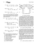
+ Cr(Z?s - Z?ur + b? ) - Ktr(Zur - Zrr) Fig. 2. Active half-car model
For active suspension system shown in Fig. 2, the hydraulic III. CONTROL METHOD
actuator forces Fa1 and Fa2 at the front and rear suspension
system are generated respectively. Therefore, equations of The suspension system electronic control was designed in a
motion can be written [8]: way that the damping energy can be improved against different
road disturbances like bumps or potholes. The suspension
MsZ¨s = -Kf (Zs - Zu f - a? ) - Cf (Z?s - Z?u f - a? ) control system relies on a control unit to control the operation
- Kr(Zs - Zu f + b? ) -Cr(Z?s - Z?ur - b?? ) + Fa1 + Fa2 of the hydraulic actuator. In Fig. 2, suitable sensors located
on the car body send signals reflected road disturbances and
(5) then the signals feedback to a reference point to compare a
specific actual signal with the set point. Accordingly, the
Is? = aKf (Zs - Zu f - a? ) + aCf (Z?s - Z?u f - a? ) control unit can moderate the output variables to acceptable
ranges. In this study, two different types of PID (Proportional-
- bKr(Zs - Zur + b? ) (6) Integral-Derivative) controllers are used to control a half-car
model. The first type of PID controller is a conventional
- bCr(Z?s - Z?ur + b?? ) - aFa1 + bFa2 PID controller as shown in Fig. 3. This controller can be
represented in time domain by the following equation [24]:
Mu f Z¨u f = Kf (Zs - Zu f - a? ) + Cf (Z?s - Z?u f - a?()7) u(t) = Kpe(t) + Ki te(t)dt + Kd(de(t)/dt) (9)
- Kt f (Zu f - Zr f ) - Fa1
MurZ¨ur = Kr(Zs - Zur + b? ) + Cr(Z?s - Z?ur + b? ) (8) The second type of PID controller is shown in Fig. 4.
- Ktr(Zur - Zrr) - Fa2 This controller is a modified form of the conventional PID
controller and can be formed by moving the proportional and
Where; derivative parts from the main forward path to the feedback
Zs f : sprung mass displacement at front body(Zs - a? ) path to operate on a measured signal y(t). In the meantime,
Zsr : sprung mass displacement at rear body(Zs + b? ) keeping the integral part in the main forward path to operate
Zs : sprung mass displacement on error e(t). In result, the controller is converted to an I-PD
Zu f : unsprung mass displacement at front body controller form [25].
Zur : unsprung mass displacement at rear body
Zr f : road input to front wheel The modified PID controller has the ability to eliminate
Zrr : road input to rear wheel the kick of error or impulse function that associated with using
? : vehicle rotational movement (rad) the conventional PID controller generated at the time the set
Fa1 : front actuator force (Newton) point change [24],[26]. Thus, a preferred tracking reference
Fa2: rear actuator force (Newton) can be obtained by using the modified PID controller [27].
The time domain equation of the modified PID controller is
given by [24]:
u(t) = -Kpy(t) + Ki te(t)dt - Kd(de(t)/dt) (10)