
Page 24 - 2023-Vol19-Issue2
P. 24
20 | Taheri
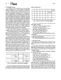
B. Embedding Process matrix is shown in Fig. 3
It is finished up from the exploration that many embedding
Fig. 3. A block of 8×8 DCT Coefficients Matrix
image are embed in the HL sub band and HH sub band of
the detail coefficients of wavelet transform for boost robust- 5) A bit of scrambled watermark is embedded in DCT
ness against statistical attacks and robustness against visual block matrix as follows:
attacks or impalpability. Coefficients of HH sub band of a
degree of IWT are chosen for embedding image embedding i f W ”(i, j) = 1 then i f POI(1, 8) < POI(2, 7)
for accomplishing better the robustness against attacks. After then swap PWI(1, 8) with POI(1, 8)
this, on the arrangement of decided HH coefficients of wavelet i f W ”(i, j) = 0 then i f POI(1, 8) = POI(2, 7)
transform, discrete cosine transform is applied and embedding then swap PWI(1, 8) with POI(1, 8)
image is embedded utilizing trading of mid-band coefficients. W ”(i, j):The scrambled watermark bit
The LL sub groups connote the attributes of image while HH POI:The original image coefficient
sub groups imply the clamor level in image. For imperceptible 6) Apply inverse discrete cosine transform on each em-
image stowing away, HH frequency sub groups are chosen bedded block.
for stowing away contrasted with Low frequency groups in 7) Apply inverse integer wavelet transform to get water-
light of the fact that embedding in HH doesn’t change the marked image in spatial domain.
vital qualities of image. The point by point embedding system The watermark embedding procedure is shown in Fig. 4.
of proposed method is made sense of as following.
C. Extracting Process
1) The watermarking image as the training signal input According to the embedding process, watermark can be
hopfield network in order to finish the watermark storage;
extracted through the corresponding inverse operation as fol-
2) The watermark signal R is gotten after the watermark lows:
signal doing scrambling transform. The affine transform is
used as scrambling transform, the key is scrambling times, 1) The watermarked image and the original image are
and then the watermark pretreatment is completed. processed by three- level IWT, DCT is performed on selected
HH3 sub-band coefficients block of each image, then specific
3) The original image is read and transformed using in- DCT coefficients of each block {(P (1,8) and P (2,7)} for two
teger wavelet transform which decomposes image into 4 dif- images are selected.
ferent frequency bands. Integer wavelet transform is applied
again on all above sub-bands for decomposing into 16 sub- 2) The scrambled watermark bit is extracted according to
bands and four HH2 (HH sub-bands at level two) sub-bands the following algorithm:
is selected. Integer wavelet transform is applied again on
selected four HH2 sub-bands for decomposing into 16 sub- i f PWI(1, 8) > PWI(2, 7) then W ”(i, j) = 1
bands and four HH3 (HH sub-bands at level 3 i.e. HH31, else i f PWI(1, 8) > POI(1, 8) then W ”(i, j) = 1
HH32, HH33 and HH34) sub-bands are selected. These diag- i f PWI(1, 8) = PWI(2, 7) then W ”(i, j) = 0
onal coefficients (HH sub-bands) are selected achieving better else i f PWI(1, 8) = POI(1, 8) then W ”(i, j) = 0
imperceptibility and robustness in order to achieve least dis- W ”(i, j):The extracted watermark bit
tortion in cover image in embedding of secret Image. Selected PWI:The watermarked image coefficient
4 HH sub bands for embedding are shown in Fig. 2. 3) The extracted watermark is gotten through the extracted
watermark signal R’ is processed by hopfield network accord-
Fig. 2. Four Selected HH sub-bands for embedding ing to the key inverse scrambling. Watermark post-processing
process is that at the beginning of the watermark signal ex-
4) Perform discrete cosine transform at 8×8 block level tracted is blocked and transformed according to watermark
on all above selected HH3 sub-bands and 3×3 blocks of IWT- training methods. The input set is gotten. R’ is put into hop-
DCT domain is achieved, A block of 8×8 DCT coefficients field network what storages the original watermark. Through